Noise Injection into Cooling Pipe
| Module |
Position |
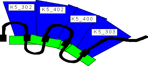
| K5-302 |
O10 low |
| K5-402 |
O11 high |
| K5-400 |
O12 low |
| K5-303 |
O13 high |
Ned Spencer's grounding scheme
Noise Injection over a transformer into the cooling
pipe. In between the transformer and the cooling pipe is a resistor, to
measure the voltage drop, from which the current conduction could be calculated.
Thermistor Temperature: 40 deg. C
Macros to analyse the data are provided by Joern.
1.) Measurements with sinus-waveformgenerator Wavetek
395 (as a loan from the barrel systemtest)
a.) different
Frequencies 4Mhz, 10Mhz, 20Mhz, 30Mhz and 40Mhz
the current through the cooling pipe was for all measurements set to 50mA
peak to peak.
Difference
in inputnoise
The highest increment for the inputnoise
could be found for 10Mhz, but also for 20MHz and 30Mhz an increment could
be observed. For 4MHz and 40Mhz the increment is small.
b.) different currents:
12mA, 24mA, 36mA, 48mA and 60mA
@
10MHz
@30MHz
!!!!
1Vpp is equivalent to 6mA !!!
2.) Measurements with HP-Pulser 8012B
Because the Wavetek 395 was needed at the barrel
systemtest and we could not get a working wave-generator from the electronic
pool, a hp-pulser was used to inject the current into the pipe. The time
dependece of the current through the pipe has a small similarity with a
sinusfunction ........
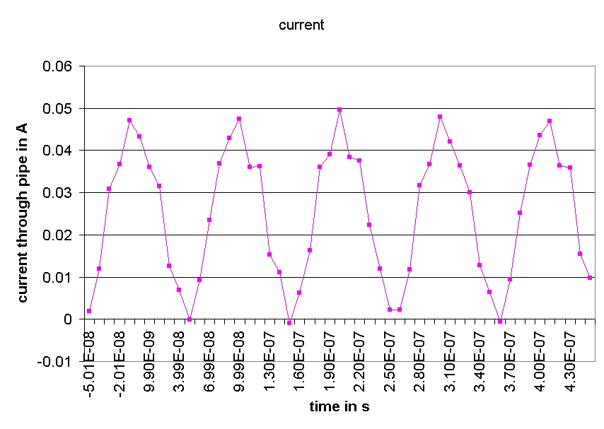
However, the current was not changed for the following
measurements
Difference without noiseinjection / with noiseinjection
Conclusions
-
Noise was injected into the cooling pipe and could
be observed as aditional noise in the modules.
-
Structure of Noiseinjection different for the modules/positions/frequencies
(10MHz seagull for 302 and 303)
-
10Mhz: the noiserise of the two modules on the deep
cooling-blocks is in average the double of the noiserise of the modules
in the upper positions. (low statistic!)
NEW RESULTS
Further Noise injection studies (P.Bernabeu, P.Dervan & A.Greenall)
-
Noise injection procedure, as outlined above. 6MHz Sine Wave injected onto
the cooling pipe.
-
All modules have cooling block and Spine shunt shields implemented.
-
Diagram showing module position and cooling pipe
profile.
-
Excess noise profile is shown for all 4 modules.
The procedure was then repeated but this time with the 2 'upper' modules
K5-402 and K5-303 swapped - this was done to check whether the noise profile
was position dependant and not module. The repeated noise profile plot
can be seen here.
Module K5-402 was then modified so that the cooling block shunt shield
was short-circuited to module AGND - this is not truely representative
of Tony Smith's grounding scheme as PP0 (patch panel 0) DGND was connected
to the radial foils and the power supply cables screen connected to DGND
return. Noise injection was then repeated, with all 4 modules back into
their original positions, this noise profile can be found here.
Observations
With the cooling block shunt shield:
-
Geometry of the cooling blocks and pipes can be clearly seen.
-
Excess noise can be seen at the edges of all modules, even where there
is no overlapping module(s) present.
With the shunt shield bypassed, on a single module only - all the others
still having their shunt shield(s):
-
Module without shunt shield shows significant drop in excess noise - noise
profile is flattened with also little evidence of excess noise at edges.
-
There is also a global effect across all modules with their excess noise
being reduced.
The action of swapping K5-402 and K5-303 highlights an apparent difference
in module 'type' (Cicorel or Dyconex) performance and their suscesptibility
to noise pick up!
Systemtest status
All 4 Outer modules have now been modified so that the cooling block shunt
shield can either be implmented or short-circuited to AGND. This should
allow further tests to continue in the evaluation of module performance
with respect th the differing grounding/shileding schemes.