
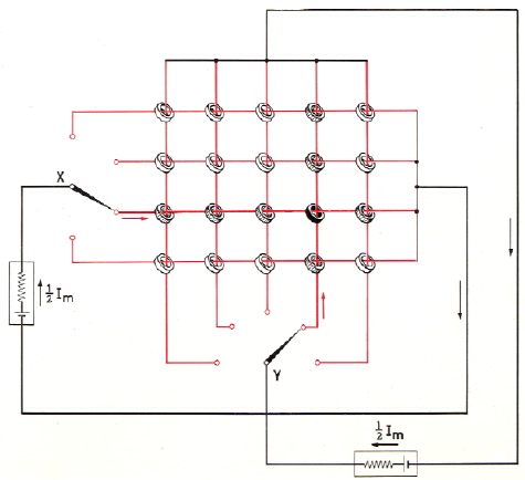
The complete set as illustrated is called a 'memory plane' or 'matrix plane' and in actual installations it would have many more than the 20 cores shown in the diagram. A small memory will have four such planes, stacked one above the other; larger memories have stacks of up to 100 planes. It is seen that switches are provided whereby current pulses can be sent through the X-wire threaded through any selected horizontal row of ring core elements, and through the Y-wire threaded through any selected vertical column of elements. In practice, these switches consist of external devices, such as punched-card systems, for example.
The operation of a single memory plane can be simply understood by remembering that, at any given time, each of the ring cores is either in the condition 0 or in the condition 1. If, with the switches in the positions shown in Fig. 7, a current pulse corresponding to a magnetising field of + 1H*) is passed through the Y-wire of the fourth column from the left as indicated by the position of switch Y, and a similar current is at the same time passed through the X-wire of the third row from the top as indicated by the position of switch X, only the one core, situated at the point where the fourth column and the third row cross each other (shown in black in the diagram) will be subjected to the full magnetising field of (1/2H) +
*) In the following to he referred to as 1/2 Im.
(+1H) - +H. If that core was originally in the condition 0 it will immediately change to condition 1. If, however, it was originally in condition 1 it will remain in that condition.
All the other ring cores in the fourth column and the third row will receive only +1/2Im pulses and will not change their condition. These so-called halfselected cores are drawn with hatched shading. All the other cores in the memory plane receive no pulses and, evidently, they do not change their condition. It will also be clear that if - 1Im pulses are passed through the same X- and Y-wires the selected core would, if originally in the 1 condition, change to the 0 condition or, if o nally in the 0 condition,will remain in that condition.