


Next: Charge collection efficiency
Up: The effects of radiation
Previous: The detectors
The effect of all three types of irradiation on the reverse current characteristics of the GaAs detectors is small.
Figure 1:
The reverse current characteristics of a 210 m thick GaAs detector with increasing 24GeV/c proton fluence, measured at 20oC
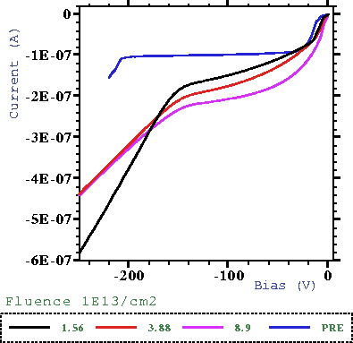 |
Figure 1 shows four reverse current characteristics with increasing proton fluence for a 210m thick detector measured at 20oC. The plateau current after a fluence of 8.9  1013 p/cm2 is only 2.2 times larger than the pre-irradiated value. Before irradiation the detector is fully depleted at a bias, Vfd, of 250V; after only 1.56 1013 p/cm2 this has reduced to 160V. The value remains unchanged with higher fluence. For an applied bias greater than Vfd the signal created by irradiating the ohmic contact with an alpha source (the hole signal) is non-zero, implying that the detector is active across the entire bulk. As the value of Vfd is reduced with fluence the extension of the high field region in the detector changes after irradiation.
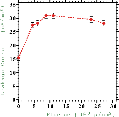
The value of the reverse current for biases greater than Vfd reduces with increased fluence and the reverse current characteristic becomes more resistive in nature. Although the reverse current at Vfd increases with dose up to 1 1014 p/cm2, the majority of the increase occurs by 3 1013 p/cm2. From 1 1014 p/cm2 up to 2.4 1014 p/cm2 (the maximum fluence tested with this sample) the current at this bias remains approximately constant (see figure 2).
Figure 2:
The reverse current of a 160m thick GaAs detector as a function of fluence of 24GeV/c protons, measured at 20oC.
 |
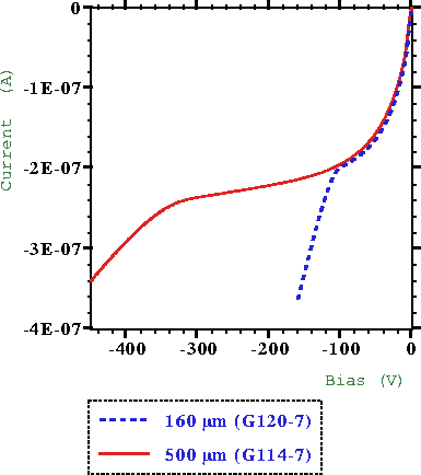
Reverse current characteristics of two detectors of different thickness, 160m and 500m, both of which were irradiated to 6 1013 p/cm2 are shown in figure 3. It can be seen that the value of the leakage current up to Vfd is independent of the detector thickness. This is not the case in silicon where the leakage current, Ir, has a dependence on fluence,  , given by [6]
|  |
(1) |
where  is the reverse current damage constant and Vol is the volume of the detector. No varriation in this effect on the leakage current has been observed for detectors that were biased during irradiation.
Figure 3:
The reverse current characteristics of two GaAs detectors after 6 1013 24GeV/c protons/cm2.
 |
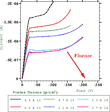
The forward current characteristics also change with increasing fluence. The effect of protons on a 160m thick detector, shown in figure 4, illustrates this. A plateau appears that extends to higher bias values with increasing fluence while the magnitude of the plateau current falls. This allows the detector to be operated under forward bias.
Figure 4:
The forward current characteristics of a 160m thick GaAs detector with increasing 24GeV/c proton fluence, measured at 20oC
 |
Next: Charge collection efficiency
Up: The effects of radiation
Previous: The detectors
latex2html conversion by www person on 1997-08-27