Application to the VELO
2. VELO algorithm (Part I)
A. The problem(s)
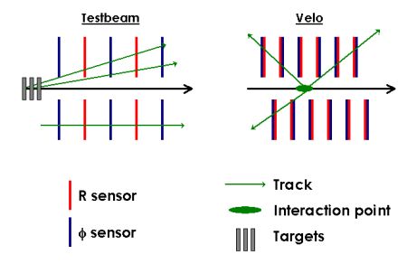
The VELO case is quite different than the TestBeam case. The main difference is the position of the interaction point, as illustrated on Fig.1.
1. VELO vs Telescope (as described in note
LHCb 99-032)
In the testbeam case, we have only
FORWARD tracks, as in the real situation we will also deal with
BACKWARD tracks. Thus, in the real case, we have
FOUR slightly uncorrelated parts: Right Forward (
RF), Right Backward (
RB), Left Forward (
LF) and Left Backward (
LB).
However, if we consider the interaction point Z spread (5 cm), the possibility of having tracks crossing both parts is not negligible, and as shown in next part, it's even possible to perform a relatively correct internal box alignment with only those tracks. For more informations about the backward/forward problem, have a look at the presentation I gave during the
T-Rec meeting on 09/05/05.
In terms of precise alignment however, backward tracks are not satisfactory, as they didn't contain any information on momentum. That's one of the reasons why we also aim to use beam halo tracks. These tracks behave like the testbeam one, so they could provide us an elegant solution to the 'backward puzzle'. More details about that are given in part C.
B. Proposed strategy
First step is to align internally the stations in each halves. This operation, if we could use Millepede, should be quick and then would be apply even for the online alignment.

2. The VELO alignment strategy
The proposed strategy is summarized on Fig.2. It is divided into 2 distinct parts: STEP1, using tracks only, is intended to provided internal alignment of the VELO modules into each half of the VELO. Then, boxes are aligned together during STEP2, using overlap tracks and primary vertices. STEP1 results are now fully described in
LHCb-2005-101 note, most recent results are available on this webpage (next part). STEP2 latest results are also available on this page, and will be soon summarized in a LHCb note.
C. VELO alignment with halo particles: more precisions
As said in the previous part, using halo particles could provide us an elegant an efficient way to improve the internal alignment of our detector. It will definitely provide more interesting informations on the backward areas.
But halo tracks will also be of great support for STEP2 alignment. Indeed we intend to use overlap tracks at this stage, and as we will see in the part dedicated to STEP2, halo tracks provide good overlap candidates.
This case is currently studied, as it will be very close to the 2006 system test (aka ACDC). A testbeam simulation is now coded, along with a specific software chain (pattern recognition + alignment ) for halo particles (see
Tomas's talk at last VELO meeting for more info about that).
...Go to the next part...